


|
We have Siemens, Haas, Fanuc, Heidenhain, Agie, Robofil & Panasonic Controls. None of these controls offers, even aproximately, the features of LinuxCNC. We managed to transform our Siemens hard driven VMC into an operator gentle machine, with possibilities never dreamt of. Thank you LinuxCNC.org and Mesa Electronics. |
|
Connecting with the Parallel Port #1.How we handled the Parallel Port #2.What is connected to the Parallel Port #3.Parallel Port Tester #4.Parallel Port Driver #5.ptest.hal #6.ptest.xml #7.C10 Webpage.htm #8.C10R10 Estop #9.C10R10 Limit Switches #10.C10R10 Wiring an MPG #11.C10R10 Wiring Guide Steppers #12.C10R10_USER_MANUAL #13.C10R10_Wiring Guide.pdf #14.Ptestbis.png #15.ptestbis.hal #16.ptestbis.xml | 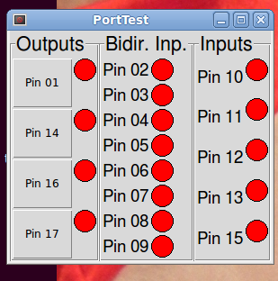 |
|
Norte Config Files #1.Norte03.zip | 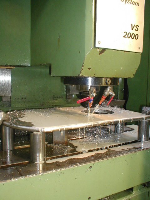 |
|
LinuxCNC Spindle Orientation #1.How we orient our Spindle. #2.Story of a Builder. #3.Spindle Orientation. #4.orient-ini-01. #5.orient-ini-02. #6.orient.ini-03. #7.orient.ini-04. #8.orient.ini-05. #9.orient.ini-06. #10.Orient.9. #11.Core Components. | 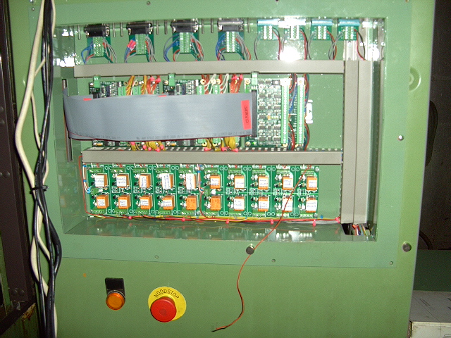 |
|
LinuxCNC 4th AXIS PREPARATION #1.Leadshine Stepper Drive DM856. #2.Leadshine SPS Power Supplies #3.Leadshine SPS407 220VAC 50Hz 300W #4.NEMA 34 Stepper Motor 920oz 80VDC 5 6A Digital Drive | 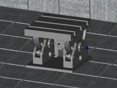 |
|
LinuxCNC Second Parallel Port #1.How we handled the existing Parallel Port #2.A second Parallel Port on LinuxCNC. #3.LinuxCNC Documentation Wiki NetMos. #4.PCI Parallel Port. | 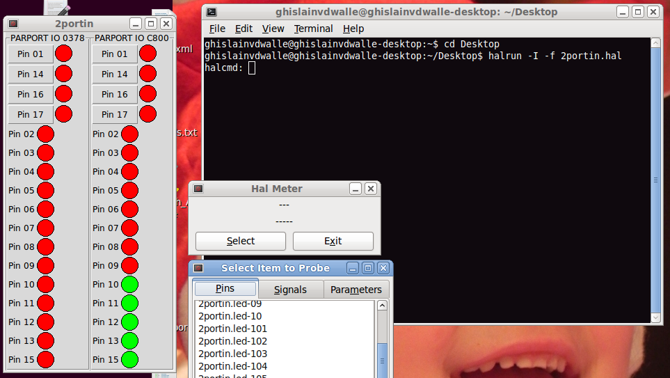 |
|
LinuxCNC Serial and USB Port #1.How we handled the Serial and USB Port #2.7680_Labs_2013.pdf Gives insight in the basics. #3.Controlling coolant w serial port (1 3). #4.Informatique Softwares LinuxCNC Recettes Relais sur un arduino. #5.Select a serial port. #6.Serial HOWTO Interesting Programs You Should Know About. #7.Serial HOWTO Serial Port Basics. #8.SERPORT. #9.Set serial port pin high using python. |
|
Replacement of the Siemens Spindle Drive 6RA26 On 05/2015 our Siemens Spindle drive went faulty. The schematics are here: #1.Siemens 6RA2601.JPG #2.Siemens 6RA2602.JPG #3.Siemens 6RA2603.JPG #4.Siemens 6RA2604.JPG (here is the faulty transformer) #5.Siemens 6RA2605.JPG #6.Siemens 6RA2606.JPG #7.Siemens 6RA2607.JPG The pictures with the settings of the potentiometers are here: #8.Siemens 6RA2608.jpg #9.Siemens 6RA2609.jpg #10.Siemens 6RA2610.jpg #11.Siemens 6RA2611.jpg We bought a second hand drive here: #12.Siemens 6 RA 2625 6DV57 Drive.html The Cabling to connect is here: #13.Simoreg Bekabeling1.JPG #14.Simoreg Bekabeling2.JPG In our quest to repair the faulty drive, we found the fault here= #15.Siemens 6 RA 2625 6DV57 Drive.html And ordered the print here: #16.Siemens Simodrive Card C98043 A 1087 L1 .html |
Replacement of the Siemens X-Y-Z Servo Drives
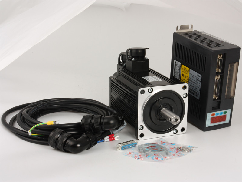
After some search we decided to replace them with the following material:
#2.KRS Servo drives. Info about simular drives, which hopefully helps to decypher the chinese manual. #2.1CNC ServoControl. #2.2EP1C MANUAL sold by Vital Systems. #2.3Servo Tuning Tutorial. #2.4AC Servo Driver Manual Brief/decyphered from the Chinese Manual. #2.4.1.Connections to the DB-25 Connector of the Servo Drive.  pin 6 : GND pin 9 : 24VDC Servo On pin 13: Analog +-10VDC pin 25: Analog +-10VDC #3.The Alibaba Order. This became a struggle, because the supplier sent at first the wrong material: 750W 3A AC Servo Motor 3000RPM Single-Phase 80ST-M02430 AC Servo Motor + Servo Motor Driver. Finally it became twice as expensive as originally thought it would be. On the other hand, even in this case it is very cheap compared to Siemens and Yaskawa. After playing around with the material, we are impressed about the quality of the material. Only the manuals are in Chinglisch (very poor translated English).
#4.AC Servo: Analog or Step_Dir? - LinuxCNC. #5.Servo Tuning Help - Page 2 - LinuxCNC. #6.The data for using Halscope for the PID fine tuning are: axis.0.joint-vel-cmd for the speed of joint 0 axis.0.f-error for the drag "=sleepfout" axis.0.joint-pos-fb for visualisation of the total movement #7.The link for the Halscope Tutorial The Result of the Servo Tuning for the X-Y-Axis: #7.1.Norte03-ini dd 30-05-2018. After Setting the Software Stops the reach of the machine becomes: X-Axis;+10 & -1180 = 1190mm Y-Axis;+30 & -440= 470mm This seams satisfactory and will increase easy handling. #7.2.Norte03-ini dd 30-05-2018(2). After completing the assembly of the Z-Axis Servo and Drive the ini becomes: #7.3.Norte03-ini dd 05-06-2018.
DC Siemens Servo Motors, a mechanical adaptation is necessary. #8.A view of the present Assembly of the X and Y Axis. #9.Existing Siemens DC Servomotor. #10.Existing Coupling.pdf. #11.Machine Housing Y Axis. #12.130ST-M15015 Servomotor. #13.Adaptor. #14.Coupling New. #15.Assembly Plate Holding Brake. #16.Assembly Plate Z-Axis Servomotor. #17.Pressure Plate.pdf.
#18.380V to 220V Electronic Output Transformer for 7KW Servo Drive. "Vorschub Simoreg Ein" De stroomverzorging wordt geschakeld door Relais K1-K11 (K1 Blatt 1) 380V gaan naar Trafo T11 en spijzen 3 x 165V in de Transistor Gleichsteller #19.DB25 Male 25Pin Breakout Board. #20.Cable DB15 male to female 10m. #21.10 FEET - Electrical Conduit Channel. #22.FLEXIBLE CABLE 4 CORE. #23.Power Supply 45W 54-90VDC 500mA MEANWELL. #23.1.Manual Power Supply 45W 54-90VDC 500mA MEANWELL. #24.90V Power Supply 4.4A 400W.
We need for the Z-axis a holding brake. None of the Chinese Suppliers was capable to supply an integrated one in the servomotor. So we bought an external Holding Brake. #25.Ogura Clutch MNB 4-03 DC-90V.. #26.Ogura Holding Brake MNB Drawing. #27.Ogura Holding Brake Installation Video.
#29.K1 Blatt 1. #30.K1 Blatt 2. #31.K2 Blatt 1. #32.K3 Blatt 1.
The additional wiring we bought has to be consitent with these rules as follows:
|  |
Replacement the Heidenhain Linear Scale.
#2.Sino Linear Scale Aliexpress Order.
|